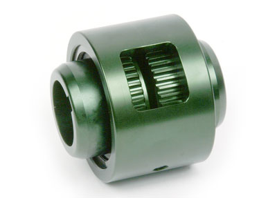
Continuous Sleeve (C, CMM, CSPCR, CCS, & CSHP Types)
- Simple, inexpensive all steel type gear coupling
- Most standard configurations available from stock
- Load capacities up to 2,520,000 in-lbs (284700 Nm)
- Patented BUNA N seal design

Continuous Sleeve (C, CMM, CSPCR, CCS, & CSHP Types) Additional Resources
Standard C Type
- Basis for all types of Lovejoy / Sier-Bath Continuous Sleeve Couplings
- Low profile compact design is easy to implement
- Single (flex-rigid) or double (flex-flex) engagement
Mill Motor CMM Type
- Designed with longer universal hub on one end to accommodate straight or tapered shafts
- Standard hub and sleeve on the other end
- Universal hub bored to customer specifications
- Available with longer universal hubs on both ends
Floating Shaft CFS Type
- Two flex-rigid couplings connected by an intermediate shaft
- Increased capability to accommodate parallel misalignment
- Allows for longer shaft separations
Spacer CSPCR Type
- Drop-out spacer design allows for ease of maintenance without disturbing the equipment mountings
- Spacer has rigid teeth to mate with sleeves on each coupling
- Increased capability to accommodate parallel misalignment
- Allows for longer shaft separations
Cut-out Shifter CCS Type
- Designed for quick disengagement between the driver and driven equipment
- Special seal in disengagement hub to prevent undue friction when hub turns in sleeve
- Widely used on dual drive operations and equipment operating in tandem
- Available with pins to maintain sleeve in engaged and disengaged positions
- Shifting mechanisms available upon request
Shear Pin CSHP Type
- Designed to limit and protect against excessive torque or sudden shock loads
- Sheer pins designed and manufactured for predetermined loads
- Pins are inserted in hardened bushings to minimize wear
- Easy to install new pins
|
|
Nominal |
Max Speed |
ID1-ID2 |
Weight |
Parallel |
Angular |
|||||||
|
|
Torque |
Unbal |
Bal |
Max Bore |
Rough Stock Bore |
|
|
Misalignment |
Misalignment |
||||
|
Size |
In-lb |
Nm |
RPM |
RPM |
in |
mm |
in |
Mm |
lbs |
kg |
in |
mm |
Degrees |
|
7/8 |
2,500 |
300 |
6,000 |
18,000 |
1.25 |
31 |
0.44 |
11 |
5 |
2 |
0.005 |
0.13 |
1/2° per Mesh |
|
1.5 |
7,600 |
900 |
5,000 |
15,000 |
1.63 |
42 |
0.63 |
16 |
8 |
4 |
0.007 |
0.18 |
1/2° per Mesh |
|
2 |
20,200 |
2300 |
4,200 |
12,600 |
2.13 |
56 |
0.73 |
19 |
13 |
6 |
0.007 |
0.18 |
1/2° per Mesh |
|
2.5 |
30,200 |
3400 |
3,750 |
11,250 |
2.63 |
70 |
0.88 |
22 |
20 |
9 |
0.007 |
0.25 |
1/2° per Mesh |
|
3 |
50,400 |
5700 |
3,600 |
9,000 |
3.13 |
84 |
1.19 |
30 |
33 |
15 |
0.010 |
0.30 |
1/2° per Mesh |
|
3.5 |
88,200 |
1000 |
2,800 |
8,400 |
3.63 |
97 |
1.25 |
32 |
63 |
29 |
0.012 |
0.30 |
1/4° per Mesh |
|
4 |
126,000 |
14200 |
2,400 |
7,200 |
4.13 |
111 |
1.75 |
44 |
91 |
41 |
0.012 |
0.30 |
1/4° per Mesh |
|
4.5 |
184,000 |
20800 |
2,200 |
6,600 |
4.75 |
130 |
2.38 |
60 |
126 |
57 |
0.007 |
0.18 |
1/4° per Mesh |
|
5 |
270,900 |
30600 |
2,100 |
6,300 |
5.75 |
160 |
2.88 |
73 |
195 |
89 |
0.007 |
0.48 |
1/4° per Mesh |
|
6 |
378,000 |
42700 |
2,000 |
6,000 |
6.63 |
186 |
3.88 |
99 |
267 |
121 |
0.009 |
0.23 |
1/4° per Mesh |
|
7 |
598,500 |
67600 |
1,000 |
3,000 |
7.50 |
200 |
4.69 |
119 |
320 |
145 |
0.010 |
0.25 |
1/4° per Mesh |
|
9 |
1,260,000 |
142400 |
800 |
2,400 |
9.50 |
240 |
5.88 |
149 |
520 |
236 |
0.011 |
0.28 |
1/4° per Mesh |
|
11 |
2,205,000 |
249200 |
600 |
1,800 |
11.50 |
305 |
7.75 |
197 |
925 |
420 |
0.013 |
0.33 |
1/4° per Mesh |
|
12 |
2,520,000 |
284700 |
550 |
1,650 |
12.50 |
330 |
9.75 |
248 |
1,200 |
545 |
0.014 |
0.36 |
1/4° per Mesh |
- For Flange Designs: see Flanged Sleeve
- For Nylon Sleeve (no lubricant coupling): see Nylon Sleeve
- For Large Jaw Coupling: see H Type
- For “Infinite Life”: see Disc Couplings
- Or, for other coupling types: see Coupling Preselection Guide
- For a broad overview on gear couplings in general, please consider reading: Gear Coupling Tutorial – Part I: Overview.
- To get a better understanding of gear coupling configurations, please read: Gear Coupling Tutorial – Part II: Configurations.
- To learn about mounting gear couplings, check out: Gear Coupling Tutorial – Part III: Mounting the Coupling.
- For tips and tricks on coupling selection and availability, see: Gear Coupling Tutorial – Part IV: Selection & Availability.
- To help troubleshoot or understand gear coupling failure modes, review: Gear Coupling Tutorial – Part V: Failure Analysis (with photos).

